What is the most inexpensive way that I can measure capacitance? I have some photoflash capacitors that aren’t marked with their capacitance. I went to radio shack, and the cheapest multimeter that measured it was around 60 dollars. Is there a cheap way that I can find out the rating of my capacitors?
Discussions
You’re obviously quite smart in this field, so I pose a question to you.
How do I find out how much capacitance I need? Is there an equation? I need 5v discharged over 2 seconds from a capacitor for my diy project, but no one can shoot me a straight answer to the value of the capacitance that I need. Any suggestions?
Answer 8 years ago
Jacek, check out this page:
and use the formula provided. There you enter the 5 volts as the initial voltage and then put time equals 2 seconds. Then you can solve for the RC value.
I don’t know how to measure the capacitance of a capacitor accurately but I can estimate the capacitance of a capacitor near to the actual value with cheap parts.
All you need to do is to connect a resistor with known value( in Mega ohm), a digital multimeter and the capacitor which is going to be measured in parallel.
Before you connect the capacitor with the resistor and the multimeter in parallel,
charge the capacitor with a known constant voltage source(battery work best). After the capacitor is fully charged, prepare a stopwatch and let the stopwatch start counting as soon as you connected the capacitor in parallel.
Set a voltage reference in such a way that you stop the stopwatch counting after you observed the value of the voltage reference displayed by the multimeter , ie 100mV. Record the time taken. Record the data as follows:
Initial Voltage, Vo = voltage of power source, in Volt
Resistance, R = Resistance of the resistor used, in ohm
Final voltage, V = voltage reference, in Volt
Time taken, t = The time when the stopwatch stop counting, in seconds
Then use the formula V = Vo x e^(-t/CR)
ln(V) = ln(Vo)-t/CR
ln(V/Vo) = -t/CR
ln(Vo/V) = t/CR
Finally,
C = t/[ln(Vo/V)R], in Farad
Since the capacitor and multimeter have internal resistance, the measured value will be slightly differ from the actual value. I tried it before and it does estimate the capacitance of an unknown capacitor.
Hope this can help.
Answer 9 years ago
What if during exam, i can`t remember the formula.
method one on that page is with an RC time circuit. he points out that you would never be able to actually measure this time because it’s so small, but that’s not true if you have a microcontroller like a basic stamp 2.
in an RC time circuit, the resistance in ohms multiplied by the capacitance in Farads equals time in seconds. therefore, capacitance equals seconds divided by resistance. C = T/R
here’s how the circuit would look:
—————————> to input pin of basic stamp
| |
unknown C known R
| |
—————————> to ground
so what you do is, you set the pin high for a few milliseconds to charge the cap. then you change the pin to an input, start a counter, and tell the basic stamp to watch for a logic low.
of course, you would need to “calibrate” your basic stamp first, by measuring how long it takes to go through the counting area of code. for example, tell it to go through a counting loop like ten thousand times, then time how long it takes with a stopwatch. a higher number will give you a good average after doing the calibration a few times. the basic stamp operates in milliseconds, so ten thousand loops might be close to ten seconds, but it depends on the complexity of the loop and a bunch of chaos theory variables.
so anyway, now that you know how long each count takes in your counter, you can insert the actual time in seconds into the equation to find a very good approximation of capacitance.
I would go to and order a cheap multimeter there. You can get one with capacitance function for 12$ or less with free shipping.
The circuit orksecurity describes is a lot of fun to make, and costs less than a dollar (schmitt trigger hex inverters are great, 555 timers will work too), although in my experience you need an oscilloscope (more expensive than a multimeter), or a multimeter with a frequency count function to use it with acceptable convenience and accuracy. You can keep switching in and out a bunch of known capacitances until you can’t hear a signal too. but that method does not appeal to me much!
A cheaper and more convenient method might be to MAKE SURE they are discharged first, then charge them with a 9v or 12v battery, and connect them in series to a resistor and an LED. You will have to know how to do math and use a stopwatch.
From the LED datasheet you can see the voltage drop across the LED (or use a multimeter with a diode test function). When the applied voltage drops below this threshold it will turn off. The voltage output of a capacitor across a resistor is a decay function as described here:
You are basically using the LED as a primitive voltage indicator. I suggest red due to low theshold voltage. The time the LED stays on will let you calculate the capacitance, as you now know the time it took to decay from a known initial voltage to a known final voltage across a known resistance. A bigger resistor will give more accurate results (due to the internal resistance of the capacitor and longer times the LED will be on) but the LED will be dimmer; find a good balance. Try a few hundred ohms first.
Of course if you have a multimeter with a voltage measurement function, just connect it in parallel across the capacitor instead (at a 9v or 12v charge this is no problem), this will be much more sensitive than an LED. You will see the voltage drop as it decays across the resistor and you can time it to some arbitrary point.
In my (limited) experience and (very limited) memory, camera flash capacitors are rated somewhere near 330v and vary in capacitance from approximately 100 to 300 microfarads. Knowing the capacitance does not tell you the safe voltage rating, be VERY AWARE of this. Connecting them in series and naively assuming this increases the voltage tolerance can also lead to disastrous failures.
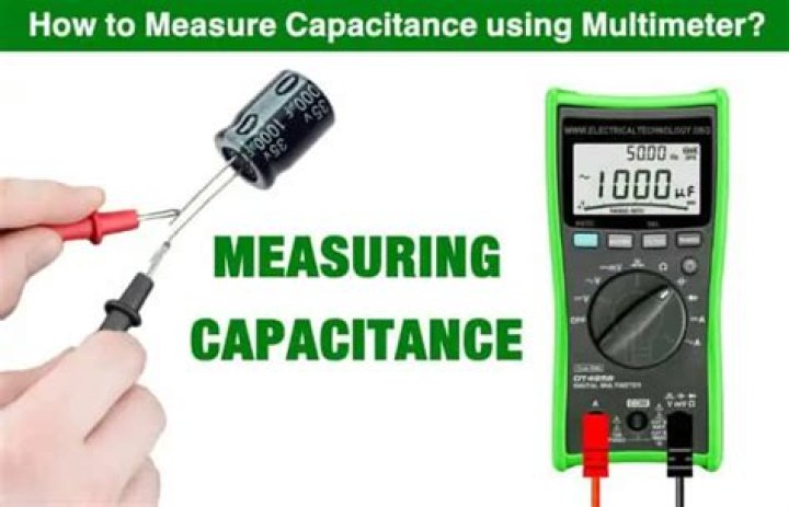
A multimeter determines capacitance by charging a capacitor with a known current, measuring the resulting voltage, then calculating the capacitance.
Warning: A good capacitor stores an electrical charge and may remain energized after power is removed. Before touching it or taking a measurement, a) turn all power OFF, b) use your multimeter to confirm that power is OFF and c) carefully discharge the capacitor by connecting a resistor across the leads (as noted in the next paragraph). Be sure to wear appropriate personal protective equipment.
To safely discharge a capacitor: After power is removed, connect a 20,000 Ω, 5-watt resistor across the capacitor terminals for five seconds. Use your multimeter to confirm the capacitor is fully discharged.
- Use your digital multimeter (DMM) to ensure all power to the circuit is OFF. If the capacitor is used in an ac circuit, set the multimeter to measure ac voltage. If is used in a dc circuit, set the DMM to measure dc voltage.
- Visually inspect the capacitor. If leaks, cracks, bulges or other signs of deterioration are evident, replace the capacitor.
- Turn the dial to the Capacitance Measurement mode. The symbol often shares a spot on the dial with another function. In addition to the dial adjustment, a function button usually needs to be pressed to activate a measurement. Consult your multimeter’s user manual for instructions..
4. For a correct measurement, the capacitor will need to be removed from the circuit. Discharge the capacitor as described in the warning above.
Note: Some multimeters offer a Relative (REL) mode. When measuring low capacitance values, the Relative mode can be used to remove the capacitance of the test leads. To place a multimeter in Relative mode for capacitance, leave the test leads open and press the REL button. This removes the residual capacitance value of the test leads.
Capacitance measurement overview
Troubleshooting single-phase motors is one of the most practical uses of a digital multimeter’s Capacitance Function.
A capacitor-start, single-phase motor that fails to start is a symptom of a faulty capacitor. Such motors will continue to run once operating, making troubleshooting tricky. Failure of the hard-start capacitor for HVAC compressors is a good example of this problem. The compressor motor may start, but soon overheat resulting in a breaker trip.
Single-phase motors with such problems and noisy single-phase motors with capacitors require a multimeter to verify properly functioning capacitors. Almost all motor capacitors will have the microfarad value marked on the capacitor.
Three-phase power factor correction capacitors are typically fuse protected. Should one or more of these capacitors fail, system inefficiencies will result, utility bills will most likely increase and inadvertent equipment trips of may occur. Should a capacitor fuse blow, the suspected faulty capacitor microfarad value must be measured and verified it falls within the range marked on the capacitor.
Some additional factors involving capacitance are worth knowing:
- Capacitors have a limited life and are often the cause of a malfunction.
- Faulty capacitors may have a short circuit, an open circuit or may physically deteriorate to the point of failure.
- When a capacitor short circuits, a fuse may blow or other components may be damaged.
- When a capacitor opens or deteriorates, the circuit or circuit components may not operate.
- Deterioration can also change the capacitance value of a capacitor, which can cause problems.
Capacitors are among the most useful of all electronic components. And capacitance is the term that refers to the ability of a capacitor to store charge. It’s also the measurement used to indicate how much energy a particular capacitor can store. The more capacitance a capacitor has, the more charge it can store.
Capacitance is measured in units called farads (abbreviated F). The definition of one farad is deceptively simple. A one-farad capacitor holds a voltage across the plates of exactly one volt when it’s charged with exactly one ampere per second of current.
Note that in this definition, the “one ampere per second of current” part is really referring to the amount of charge present in the capacitor. There’s no rule that says the current has to flow for a full second. It could be one ampere for one second, or two amperes for half a second, or half an ampere for two seconds. Or it could be 100 mA for 10 seconds or 10 mA for 100 seconds.
One ampere per second corresponds to the standard unit for measuring electric charge, called the coulomb. So another way of stating the value of one farad is to say that it’s the amount of capacitance that can store one coulomb with a voltage of one volt across the plates.
It turns out that one farad is a huge amount of capacitance, simply because one coulomb is a very large amount of charge. To put it into perspective, the total charge contained in an average lightning bolt is about five coulombs, and you need only five, one-farad capacitors to store the charge contained in a lightning strike. (Some lightning strikes are much more powerful, as much as 350 coulombs.)
It’s a given that Doc Brown’s flux capacitor was in the farad range because Doc charged it with a lightning strike. But the capacitors used in electronics are charged from much more modest sources. Much more modest.
In fact, the largest capacitors you’re likely to use have capacitance that is measured in millionths of a farad, called microfarads and abbreviated μF. And the smaller ones are measured in millionths of a microfarad, also called a picofarad and abbreviated pF.
Here are a few other things you should know about capacitor measurements:
Like resistors, capacitors aren’t manufactured to perfection. Instead, most capacitors have a margin of error, also called tolerance. In some cases, the margin of error may be as much as 80%. Fortunately, that degree of impression rarely has a noticeable effect on most circuits.
The μ in μF isn’t an italic letter u; it’s the Greek letter mu, which is a common abbreviation for micro.
It’s common to represent values of 1,000 pF or more in μF rather than pF. For example, 1,000 pF is written as 0.001 μF, and 22,000 pF is written as 0.022 μF.
How do digital mulitimeters (DMM) measure capacitance through their typical 10M Ohm input/output impedance?
Providing a logic level of 3.3V, attempting to measure 1F would mean a time constant of 10M seconds (R x C) thus the voltage rise in the capacitor being in immeasurable (in the noise floor.) They also do it within a second or so at 3% accuracy. How on earth is this achieved?
3 Answers 3
There are many ways to measure capacitance, If you have a waveform generator you can either use a square wave and measure the rise time. Or a sine wave and measure the current and voltage. If you know current and voltage, you know what your load is. If the load is a capacitor, you’d also need phase information. The links below go into more depth on how this is done. Instead of an waveform generator, the DMMs usually have a simpler circuit (usually only generating one or a few frequencies). Instead of an oscilloscope circuits that measure phase and amplitude to do the calculations.
The cool thing is, if you have an oscilloscope and waveform generator, you can also measure capacitance, sometimes better than a DMM. This also works for inductance to.
Source:
Source:
The capacitance of a capacitor is the ability of a capacitor to store an electric charge per unit of voltage across its plates of a capacitor. Capacitance is found by dividing electric charge with voltage by the formula C=Q/V. Its unit is Farad.
Formula
Its formula is given as:
Where C is capacitance, Q is voltage, and V is voltage. We can also find charge Q and voltage V by rearranging the above formula as:
Farad is the unit of capacitance. One Farad is the amount of capacitance when one coulomb of charge is stored with one volt across its plates.
Most capacitors that are used in electronics work have capacitance values that are specified in microfarad (µF) and picofarads(pF) . A microfarad is one-millionth of a farad, and a picofarad is one-trillionth of a farad.
What are the factors that effect the capacitance of capacitor?
It depends on the following factors:
Area of plates
Capacitance is directly proportional to the physical size of the plates as determined by the plate area,A. A larger plate area produces a larger capacitance and a smaller capacitance.Fig(a) shows that the plate area of a parallel plate capacitor is the area of one of the plates. If the plates are moved in relation to each other, as shown in fig(b), the overlapping area determines the effective plate area. This variation in the effective plate area is basic for a certain type of variable capacitor.
Plates seperation
`Capacitance is inversely proportional to the distance between the plates. The plate separation is designated d, as shown in fig(a). Greater separation of the plates produces a smaller capacitance, as illustrated in fig(b). As previously discussed, the breakdown voltage is directly proportional to the plate separation. The further the plates are separated, the greater the breakdown voltage.
Dielectric Constant of material
As you know, the insulating material between the plates of a capacitor is called the dielectric. Dielectric materials tend to reduce the voltage between plates for a given charge and thus increase the capacitance. If the voltage is fixed, more charge can be stored due to the presence of a dielectric than can be stored without a dielectric. The measure of a material’s ability to establish an electric field is called dielectric constant or relative permittivity, symbolized by ∈r.
Capacitance is directly proportional to the dielectric constant. The dielectric constant of a vacuum is defined as 1 and that of air is very close to 1. These values are used as a reference, and all other materials have values of ∈r specified with respect to that of a vacuum or air. For example, a material with ∈r=8 can result in a capacitance eight times greater than that of air with all other factors being equal.
The dielectric constant ∈r is dimensionless because it is a relative measure. It is a ratio of the absolute permittivity of a material,∈r, to the absolute permittivity of a vacuum,∈0, as expressed by the following formula:
Below given some common dielectric materials and typical dielectric constants for each. Values can vary because they depend on the specific composition of the material.
Material Typical ∈r values
- Air 1.0
- Teflon 2.0
- Paper 2.5
- Oil 4.0
- Mica 5.0
- Glass 7.5
- Ceramic 1200
The dielectric constant ∈r is dimensionless because it is a relative measure. It is a ratio of the absolute permittivity of a material,∈r, to the absolute permittivity of a vacuum,∈0, as expressed by the following formula:
The value of ∈0 is 8.85×10⁻¹² F/m.
Formula of capacitance in terms of physical parameters
You have seen how capacitance is directly related to plate area, A, and the dielectric constant,∈r, and inversely related to plate separation, d. An exact formula for calculating the capacitance in terms of these three quantities is:
Capacitance of parallel plate capacitor derivation
Consider a parallel plate capacitor. The size of the plate is large and the distance between the plates is very small, so the electric field between the plates is uniform.
The electric field ‘E’ between the parallel plate capacitor is:
Capacitance of cylindrical capacitors physics
Consider a cylindrical capacitor of length L, formed by two coaxial cylinders of radii ‘a’ and ‘b’.Suppose L >> b, such that there is no fringing field at the ends of cylinders.
Let ‘q’ is the charge in the capacitor and ‘V’ is the potential difference between plates. The inner cylinder is positively charged while the outer cylinder is negatively charged. We want to find out the expression of capacitance for the cylindrical capacitor. For this, we consider a cylindrical Gaussian surface of radius ‘r’ such that a Tags
In this article, we will go over different tests that we can use to tell whether a capacitor is good or not, all by utilizing the functions of a digital multimeter.
There are many checks we can do to see if a capacitor is functioning the way it should. We will use and exploit the characteristics and behaviors that a capacitor should show if it is good and, in thus doing so, determine whether its is good or defective.
Test a Capacitor with an Ohmmeter of a Multimeter
A very good test you can do is to check a capacitor with your multimeter set on the ohmmeter setting.
By taking the capacitor’s resistance, we can determine whether the capacitor is good or bad.
To do this test, We take the ohmmeter and place the probes across the leads of the capacitor. The orientation doesn’t matter, because resistance isn’t polarized.
If we read a very low resistance (near 0Ω) across the capacitor, we know the capacitor is defective. It is reading as if there is a short circuit across it.
If we read a very high resistance across the capacitor (several MΩ), this is a sign that the capacitor likely is defective as well. It is reading as if there is an open circuit across the capacitor.
A normal capacitor would have a resistance reading up somewhere in between these 2 extremes, say, anywhere in the tens of thousands or hundreds of thousands of ohms. But not 0Ω or several MΩ.
This is a simple but effective method for finding out if a capacitor is defective or not.
Test a Capacitor with a Multimeter in the Capacitance Setting
Another check you can do is check the capacitance of the capacitor with a multimeter, if you have a capacitance meter on your multimeter. All you have to do is read the capacitance that is on the exterior of the capacitor and take the multimeter probes and place them on the leads of the capacitor. Polarity doesn’t matter.
This is the same as the how the setup is for the first illustration, only now the multimeter is set to the capacitance setting.
You should read a value near the capacitance rating of the capacitor. Due to tolerance and the fact that (specifically, electrolytic capacitors) may dry up, you may read a little less in value than the capacitance of the rating. This is fine. If it is a little lower, it is still a good capacitor. However, if you read a significantly lower capacitance or none at all, this is a sure sign that the capacitor is defective and needs to be replaced.
Checking the capacitance of a capacitor is a great test for determining whether a capacitor is good or not.
Test a Capacitor with a Voltmeter
Another test you can do to check if a capacitor is good or not is a voltage test.
Afterall, capacitors are storage devices. They store a potential difference of charges across their plate, which are voltages. The anode has a positive voltage and the cathode has a negative voltage.
A test that you can do is to see if a capacitor is working as normal is to charge it up with a voltage and then read the voltage across the terminals. If it reads the voltage that you charged it to, then the capacitor is doing its job and can retain voltage across its terminals. If it is not charging up and reading voltage, this is a sign the capacitor is defective.
To charge the capacitor with voltage, apply DC voltage to the capacitor leads. Now polarity is very important for polarized capacitors (electrolytic capacitors). If you are dealing with a polarized capacitor, then you must observe polarity and the correct lead assignments. Positive voltage goes to the anode (the longer lead) of the capacitor and negative or ground goes to the cathode (the shorter lead) of the capacitor. Apply a voltage which is less than the voltage rating of the capacitor for a few seconds. For example, feed a 25V capacitor 9 volts and let the 9 volts charge it up for a few seconds. As long as you’re not using a huge, huge capacitor, then it will charge in a very short period of time, just a few seconds. After the charge is finished, disconnect the capacitor from the voltage source and read its voltage with the multimeter. The voltage at first should read near the 9 volts (or whatever voltage) you fed it. Note that the voltage will discharge rapidly and head down to 0V because the capacitor is discharging its voltage through the multimeter. However, you should read the charged voltage value at first before it rapidly declines. This is the behavior of a healthy and a good capacitor. If it will not retain voltage, it is defective and should be replaced.
So there you have it, 3 strong tests that you can do (all or either/or) to test whether a capacitor is good or not.
A multimeter determines capacitance by charging a capacitor with a known current, measuring the resulting voltage, then calculating the capacitance.
Warning: A good capacitor stores an electrical charge and may remain energized after power is removed. Before touching it or taking a measurement, a) turn all power OFF, b) use your multimeter to confirm that power is OFF and c) carefully discharge the capacitor by connecting a resistor across the leads (as noted in the next paragraph). Be sure to wear appropriate personal protective equipment.
To safely discharge a capacitor: After power is removed, connect a 20,000 Ω, 5-watt resistor across the capacitor terminals for five seconds. Use your multimeter to confirm the capacitor is fully discharged.
- Use your digital multimeter (DMM) to ensure all power to the circuit is OFF. If the capacitor is used in an ac circuit, set the multimeter to measure ac voltage. If is used in a dc circuit, set the DMM to measure dc voltage.
- Visually inspect the capacitor. If leaks, cracks, bulges or other signs of deterioration are evident, replace the capacitor.
- Turn the dial to the Capacitance Measurement mode. The symbol often shares a spot on the dial with another function. In addition to the dial adjustment, a function button usually needs to be pressed to activate a measurement. Consult your multimeter’s user manual for instructions..
4. For a correct measurement, the capacitor will need to be removed from the circuit. Discharge the capacitor as described in the warning above.
Note: Some multimeters offer a Relative (REL) mode. When measuring low capacitance values, the Relative mode can be used to remove the capacitance of the test leads. To place a multimeter in Relative mode for capacitance, leave the test leads open and press the REL button. This removes the residual capacitance value of the test leads.
Capacitance measurement overview
Troubleshooting single-phase motors is one of the most practical uses of a digital multimeter’s Capacitance Function.
A capacitor-start, single-phase motor that fails to start is a symptom of a faulty capacitor. Such motors will continue to run once operating, making troubleshooting tricky. Failure of the hard-start capacitor for HVAC compressors is a good example of this problem. The compressor motor may start, but soon overheat resulting in a breaker trip.
Single-phase motors with such problems and noisy single-phase motors with capacitors require a multimeter to verify properly functioning capacitors. Almost all motor capacitors will have the microfarad value marked on the capacitor.
Three-phase power factor correction capacitors are typically fuse protected. Should one or more of these capacitors fail, system inefficiencies will result, utility bills will most likely increase and inadvertent equipment trips of may occur. Should a capacitor fuse blow, the suspected faulty capacitor microfarad value must be measured and verified it falls within the range marked on the capacitor.
Some additional factors involving capacitance are worth knowing:
- Capacitors have a limited life and are often the cause of a malfunction.
- Faulty capacitors may have a short circuit, an open circuit or may physically deteriorate to the point of failure.
- When a capacitor short circuits, a fuse may blow or other components may be damaged.
- When a capacitor opens or deteriorates, the circuit or circuit components may not operate.
- Deterioration can also change the capacitance value of a capacitor, which can cause problems.
I need to measure or sense capacitance from 0 pF to 5pF, with an accuracy of 0.1pF or better. I know capacitance to digital convert chips claim to do that, but is there a simpler/easier way to breadboard a circuit to measure these ultra-low capacitances?
I have a small concentric cylinder where the outer cylinder is physically fixed (and tied to some potential) but the inner one is moving in and out. It’s this movement I need to track. The change in overlapping area between the two cylinders produces a change in capacitance. In that way, I keep track of its position at all times by monitoring the change in capacitance.
1 Answer 1
It’s quite straightforward to detect a change of capacitance of 0.1pF, as a ratio. The simplest is perhaps to build a relaxation oscillator and measure the frequency and change of frequency digitally, as the test capacitor is connected.
It’s very difficult to know exactly how much effective capacitance there is in the rest of the circuit, and any connection jigs, strays, terminals, leads that the ratio is measured with respect to.
The advantage of a relaxation oscillator is that one capacitor terminal is grounded, so the strays are relatively stable. The disadvantage is the strays can be large, quite easily large compared to 5pF.
The alternative is a 3 terminal guarded measurement, which is immune to stray capacitance on either terminal of the capacitor, and only susceptible to strays across it. The third terminal is ground. The method is as follows.
1) Apply a sinusoidal voltage with respect to ground to one terminal of the test capacitor from a known voltage. The strays from this terminal to ground are driven to exactly the same voltage, we are not interested in how much current is required to charge them, the voltage measurement is sufficient.
2) Hold the second terminal at ground, and measure the current required to do that. The most common way to do that is to use a virtual ground op-amp. The strays from the second terminal to ground are held at 0v, so no current flows into them, so the current measurement is accurate.
3) We now know the current through the capacitor for a given voltage across it. Compute the capacitance from impedance and frequency. A capacitive feedback rather than resistive on the virtual ground op-amp allows you to eliminate the frequency from the equation.
Even though the guarded measurement removes the effect of the strays to ground, any strays across the capacitor that are enhanced by your test jig, perhaps a plastic pressure pad that holds an SMD component down onto a footprint, will change the measurement compared to what it would be in circuit without that pad.
Capacitors in Parallel
Task 1:
Capacitors in Series
When capacitors are connected one after each other this is called connecting in series. This is shown below. To calculate the total overall capacitance of two capacitors connected in this way you can use the following formula:
| Ctotal = | C1 x C2 | and so on |
| C1 + C2 |
Example: To calculate the total capacitance for these two capacitors in series.
Task 2:
Three or more capacitors in series
Task 3:
Answers
Task 1
Task 2
Task 3
©Kitronik Ltd – You may print this page & link to it, but must not copy the page or part thereof without Kitronik’s prior written consent.
22 October 2019 at 07:27am
Good tasks they have helped me
03 September 2019 at 10:48am
03 September 2019 at 08:22am
This site has been helpful to many of us. Thanks kitronik!
21 February 2019 at 14:06pm
Hi, we don’t have a guide showing this at the moment, but it is something we should add. You have guessed correctly how to calculate the total capacitance for your circuit. I hope this helped.
20 February 2019 at 18:57pm
Do you have any tasks worked out with similar images as shown above? I am trying to figure out this same problem. I have two capacitors parallel to each other but also in a series with one other capacitor. Would I add the two in parallel and then use that number in the equation for the series? Any advice is helpful thank you!!
01 February 2019 at 12:16pm
This has really helped me so thanks a lot
04 January 2019 at 10:47am
I LIKE THIS CALCULATION SO MUCH
27 October 2018 at 03:49am
Very good information thank you kitronik
20 September 2018 at 10:58am
Hi Emmanuel, You can work out the capacitance of each of the areas individually and then work out how to find the total capacitance, the method would be determined by how the different areas are arranged in relation to each other. They may be in series with each other or in parallel. I hope this helps.
19 September 2018 at 01:21am
How do I work out capacitors connected in both parallel and series
16 January 2018 at 18:42pm
this is a very useful tool for my studies in electrical fundamentals. thanks
14 July 2017 at 10:41am
Hi Kean, there is still one more step of your calculation left to do, you need to divide 1 by 3 and then you will have your answer for C total. Hope this helps.
13 July 2017 at 04:54am
The formula for series capacitance does not work for 1F. If you add 1+1+1 you get 3F instead of .333F. Please explain.
19 May 2017 at 08:17am
Very very helpful site I like it.. Being a student of class 10th I understood it to how to solve the question of series and parallel combinations of conductors..
10 May 2017 at 11:00am
I love this Site. Thank you very much, i am going to write exams. now my problem on capacitors has been solved totally. thank you once again
19 April 2017 at 09:40am
This may be something that we produce a resource for at some point but for now, try google as there is already a lot of information on this online.
16 April 2017 at 14:11pm
I need more explanation about COULOUMBS LAW OF ELECLECTROSTATICS, and ITS CALCULATION.
03 April 2017 at 06:27am
I like this site it really help me
13 December 2016 at 22:05pm
Awwnnn….it really amazing it helps alot.
30 November 2016 at 09:40am
wow!! i really luv this site it is very helpfull.
01 November 2016 at 20:47pm
My problem on capacitor are solve
20 October 2016 at 16:18pm
Hi i like this calculation of series and parallel
03 May 2016 at 10:02am
Hi Douglas, The calculation examples will work regardless of the values of the individual capacitors.
25 April 2016 at 04:55am
Hi, It appears that your examples deal only in capacitors of varying capacitance. It would be useful to include examples of identical capacitors connected in series and parallel. Series Connected Identical Capacitors….. Total Capacitance= Nominated Capacitance divided by Total number of Capacitors. EG.. 3000 Farad ÷(X5 in series), …3000F/5=600F. Parrallel Connected Identical Capacitors…… Total Capacitance=Nominated Capacitance Times Total Number of Capacitors………. 3000Farad X (X5 in parallel)…3000FX5=15,000F Does away with all the “Long Division Nonsense”
01 April 2015 at 11:52am
Hi, The voltage would remain the same. Rob
12 March 2015 at 23:36pm
The explanation is clear, but what about the working voltage of two capacitors in parallel? Does it remains the same or individual capacitor voltage rating is added up. Suppose both capacitors are the same working voltage rating
Belko King Solomon
24 February 2015 at 13:23pm
this explanation is simple and easy to understand and like it.
07 December 2014 at 00:57am
So far this is the only explanation I’ve been able to understand. Thanks
23 May 2014 at 12:17pm
Thanks, I’ve corrected that now!
21 May 2014 at 22:04pm
i think task 3 is suppose to be 1.167F not 1.67F
Kitronik Newsletter
Sign up now to be the first to know about the latest products and resources!
A multimeter determines capacitance by charging a capacitor with a known current, measuring the resulting voltage, then calculating the capacitance.
Warning: A good capacitor stores an electrical charge and may remain energized after power is removed. Before touching it or taking a measurement, a) turn all power OFF, b) use your multimeter to confirm that power is OFF and c) carefully discharge the capacitor by connecting a resistor across the leads (as noted in the next paragraph). Be sure to wear appropriate personal protective equipment.
To safely discharge a capacitor: After power is removed, connect a 20,000 Ω, 5-watt resistor across the capacitor terminals for five seconds. Use your multimeter to confirm the capacitor is fully discharged.
- Use your digital multimeter (DMM) to ensure all power to the circuit is OFF. If the capacitor is used in an ac circuit, set the multimeter to measure ac voltage. If is used in a dc circuit, set the DMM to measure dc voltage.
- Visually inspect the capacitor. If leaks, cracks, bulges or other signs of deterioration are evident, replace the capacitor.
- Turn the dial to the Capacitance Measurement mode (
Capacitance measurement overview
Troubleshooting single-phase motors is one of the most practical uses of a digital multimeter’s Capacitance Function.
A capacitor-start, single-phase motor that fails to start is a symptom of a faulty capacitor. Such motors will continue to run once operating, making troubleshooting tricky. Failure of the hard-start capacitor for HVAC compressors is a good example of this problem. The compressor motor may start, but soon overheat resulting in a breaker trip.
Single-phase motors with such problems and noisy single-phase motors with capacitors require a multimeter to verify properly functioning capacitors. Almost all motor capacitors will have the microfarad value marked on the capacitor.
Three-phase power factor correction capacitors are typically fuse protected. Should one or more of these capacitors fail, system inefficiencies will result, utility bills will most likely increase and inadvertent equipment trips of may occur. Should a capacitor fuse blow, the suspected faulty capacitor microfarad value must be measured and verified it falls within the range marked on the capacitor.
Some additional factors involving capacitance are worth knowing:
- Capacitors have a limited life and are often the cause of a malfunction.
- Faulty capacitors may have a short circuit, an open circuit or may physically deteriorate to the point of failure.
- When a capacitor short circuits, a fuse may blow or other components may be damaged.
- When a capacitor opens or deteriorates, the circuit or circuit components may not operate.
- Deterioration can also change the capacitance value of a capacitor, which can cause problems.
A multimeter determines capacitance by charging a capacitor with a known current, measuring the resulting voltage, then calculating the capacitance.
Warning: A good capacitor stores an electrical charge and may remain energized after power is removed. Before touching it or taking a measurement, a) turn all power OFF, b) use your multimeter to confirm that power is OFF and c) carefully discharge the capacitor by connecting a resistor across the leads (as noted in the next paragraph). Be sure to wear appropriate personal protective equipment.
To safely discharge a capacitor: After power is removed, connect a 20,000 Ω, 5-watt resistor across the capacitor terminals for five seconds. Use your multimeter to confirm the capacitor is fully discharged.
- Use your digital multimeter (DMM) to ensure all power to the circuit is OFF. If the capacitor is used in an ac circuit, set the multimeter to measure ac voltage. If is used in a dc circuit, set the DMM to measure dc voltage.
- Visually inspect the capacitor. If leaks, cracks, bulges or other signs of deterioration are evident, replace the capacitor.
- Turn the dial to the Capacitance Measurement mode ( ). The symbol often shares a spot on the dial with another function. In addition to the dial adjustment, a function button usually needs to be pressed to activate a measurement. Consult your multimeter’s user manual for instructions.
For a correct measurement, the capacitor will need to be removed from the circuit. Discharge the capacitor as described in the warning above.
Note: Some multimeters offer a Relative (REL) mode. When measuring low capacitance values, the Relative mode can be used to remove the capacitance of the test leads. To place a multimeter in Relative mode for capacitance, leave the test leads open and press the REL button. This removes the residual capacitance value of the test leads.
Capacitance measurement overview
Troubleshooting single-phase motors is one of the most practical uses of a digital multimeter’s Capacitance Function.
A capacitor-start, single-phase motor that fails to start is a symptom of a faulty capacitor. Such motors will continue to run once operating, making troubleshooting tricky. Failure of the hard-start capacitor for HVAC compressors is a good example of this problem. The compressor motor may start, but soon overheat resulting in a breaker trip.
Single-phase motors with such problems and noisy single-phase motors with capacitors require a multimeter to verify properly functioning capacitors. Almost all motor capacitors will have the microfarad value marked on the capacitor.
Three-phase power factor correction capacitors are typically fuse protected. Should one or more of these capacitors fail, system inefficiencies will result, utility bills will most likely increase and inadvertent equipment trips of may occur. Should a capacitor fuse blow, the suspected faulty capacitor microfarad value must be measured and verified it falls within the range marked on the capacitor.
Some additional factors involving capacitance are worth knowing:
- Capacitors have a limited life and are often the cause of a malfunction.
- Faulty capacitors may have a short circuit, an open circuit or may physically deteriorate to the point of failure.
- When a capacitor short circuits, a fuse may blow or other components may be damaged.
- When a capacitor opens or deteriorates, the circuit or circuit components may not operate.
- Deterioration can also change the capacitance value of a capacitor, which can cause problems